
Tips and methods for using a multimeter
Multimeter is a tool used to test circuits and can be used to measure parameters such as voltage, current, resistance, etc. It is one of the essential tools for electronic engineers and circuit designers. Using a multimeter requires certain skills and experience. Here are some commonly used tips to help you use the multimeter better.

Tip 1: Choose the correct measurement range
Multimeters can measure voltage, current, and resistance in different ranges, so you need to choose the correct measurement range before use. The formula is as follows:
High voltage selection;
Current selection is low;
The resistance value is less than or equal to ten times the maximum range.
This mantra tells us that when measuring voltage, we should choose the highest measurement range; when measuring current, we should choose the lowest measurement range; when measuring resistance, we should choose a range that is less than or equal to ten times the maximum range.
Tip 2: Connect the correct measurement port
The multimeter has different measurement ports, which must be connected correctly to get accurate measurement results. The formula is as follows:
voltage, resistor, diode,
The black meter and red wire are connected first;
Current can be negative or positive;
The red wire of the red meter is connected to the positive current.
This mantra tells us that when measuring voltage and resistance, connect the black test pen to the black port of the multimeter and the red test pen to the red port; when measuring current, connect the red test pen to the A port of the multimeter and the black Connect the test pen to the COM port and pay attention to the direction of the current. If the current is negative, connect the black test pen to the positive pole of the current.
Tip 3: Use the conversion knob correctly
The conversion knob of the multimeter is used to select different measurement functions and needs to be used correctly to obtain accurate measurement results. The formula is as follows:
voltage, resistance, capacitor,
Choose the right gear when changing gears;
Choosing the wrong one will have serious consequences.
Remember, remember, remember again!
This mantra tells us that when using a multimeter, we must pay attention to selecting the correct conversion gear. Wrong selection will lead to serious consequences, so we must pay special attention to it.
Tip 4: Things to note when using a multimeter
The multimeter is a sensitive testing tool, and you need to pay attention to how you use it to avoid errors. The formula is as follows:
The power supply voltage must be normal;
The testing environment must be safe;
The reading should be stable.
It is reliable only when used correctly.
This mantra tells us that when using a multimeter, we need to pay attention to the stability of the power supply voltage, the safety of the test environment, and keep the reading stable. Only by using it correctly can we get reliable measurement results.
Tip 5: Frequently asked questions about using a multimeter
When using a multimeter, some problems often arise. Here are the solutions to some common problems. The formula is as follows:
Make sure before measuring,
Whether to select the correct mode.
Be sure to do so promptly after measurement.
Turn the knob back to OFF.
This mantra tells us that before using a multimeter, we must confirm whether the selected mode is correct to avoid measurement errors; after measurement, we must promptly turn the knob back to the OFF position to save battery life.
Using a multimeter requires certain skills and experience. Through learning and practice, we can master the use of a multimeter and improve the accuracy of measurements. The above tips are some commonly used tips when using multimeters, which can help everyone use multimeters better. At the same time, we also need to pay attention to safety in use and protect the safety of equipment and personnel.
① Precautions when using digital multimeters
The following general precautions must be followed during all phases of operation and maintenance of a digital multimeter.
- Before connecting any lines to the instrument, please observe all markings on the instrument.
Be careful when working beyond 60V (DC), 30V (AC) or 42V peak values. These ranges may cause electric shock. - Do not measure a voltage higher than the rated voltage (marked on the multimeter) between the terminals or between the terminals and the ground.
- Review the operation of the multimeter by measuring a known voltage.
- When measuring current, turn off the circuit power before connecting the multimeter to the circuit, and always connect the multimeter in series with the circuit.
- When connecting probes, always connect the commonly used test probe first. When disconnecting probes, always disconnect the active test probe first.
- Before opening the battery cover, remove the test probe from the multimeter.
- Do not use the multimeter if the battery cover or part of the battery cover has been removed or loosened.
- Once the low battery indicator light flashes on the screen, the battery should be replaced as soon as possible to avoid reading errors. Incorrect readings may result in electric shock or personal injury.
- Do not operate the multimeter in an explosive or flammable gas or smoke environment.
- Check the packaging for cracks or missing plastic. Something to pay special attention to is the insulation around the connector. Do not use a damaged multimeter.
- Check whether the insulation material of the test probe is damaged or the metal is exposed, and check the continuity. Do not use damaged test probes.
- Do not use repaired fuses or shorted fuse holders. To avoid a fire, line fuses should be replaced and only used with fuses that are rated for the same voltage and current and of the recommended type.
- Do not repair or perform adjustments alone. Under certain circumstances, voltage may still cause injury even if the equipment is turned off. To avoid electric shock, service personnel should not make internal repairs or adjustments unless first aid personnel are present.
- Do not replace parts or modify equipment to avoid causing other dangers.
- Do not use damaged equipment, otherwise the built-in safety protection features of the multimeter may be damaged (physical damage, entry of large amounts of moisture, or other reasons). Disconnect the power supply and use it only after maintenance training personnel confirm that the operation is safe.
- Before performing resistance, continuity, diode or capacitance tests, turn off circuit power and discharge all high voltage capacitors in the circuit.
- Use the correct terminals, functions and ranges for measurement.
- Do not measure voltage with the current measurement selected.
- Make sure the battery is inserted correctly into the multimeter and ensure the polarity is correct.
② How to use a multimeter
- Use the multimeter correctly
To use a multimeter correctly, you must be familiar with the dial before use. Two zero position adjusters, turn gently to adjust the zero position. Select the binding posts correctly and insert the red and black test leads into the correct holes.
Turn the switch to select the correct gear. Only by choosing the measuring range reasonably can the measurement reading be accurate. Look at the scale mark of the measuring range and look vertically at the surface to read accurately.
After the measurement is completed, dial the test leads and turn the switch to the high voltage position. Check the battery in the watch frequently. If it deteriorates, it will leak electrolyte. The instrument is stored in a good environment with no vibration or tide and a weak magnetic field. - Correctly use the ohm setting of the multimeter
To use the ohm scale correctly, you should know that there are eight items. The battery voltage should be sufficient and the circuit under test should have no voltage. Select the appropriate magnification level and point the needle to the middle of the scale.
Every time you change the magnification gear, you must re-adjust the resistance to zero. The measuring point of the pen tip has good contact, and the pen end of the measuring object is not touched by the hand. Measuring circuit line continuity and measurement range above kilohm.
To judge the diode components, the resistance is different at different magnifications. Measuring the transformer winding, you will feel numbness and electricity if you touch it with your hands.
- Things to note when measuring voltage with a multimeter
When measuring voltage with a multimeter, there are eight things to note. Know the internal resistance of the meter and be sure to have someone supervise it. The circuit meters under test are connected in parallel, and the range cannot be changed while the meter is powered on.
When measuring DC voltage, make sure you know the positive and negative poles of the circuit. Measure the voltage of the inductive circuit and do not cut off the power supply during this period. To test kilovolt high voltage, special test leads must be used.
The voltage between the induced electric current and the ground has a large difference in different measurement ranges.
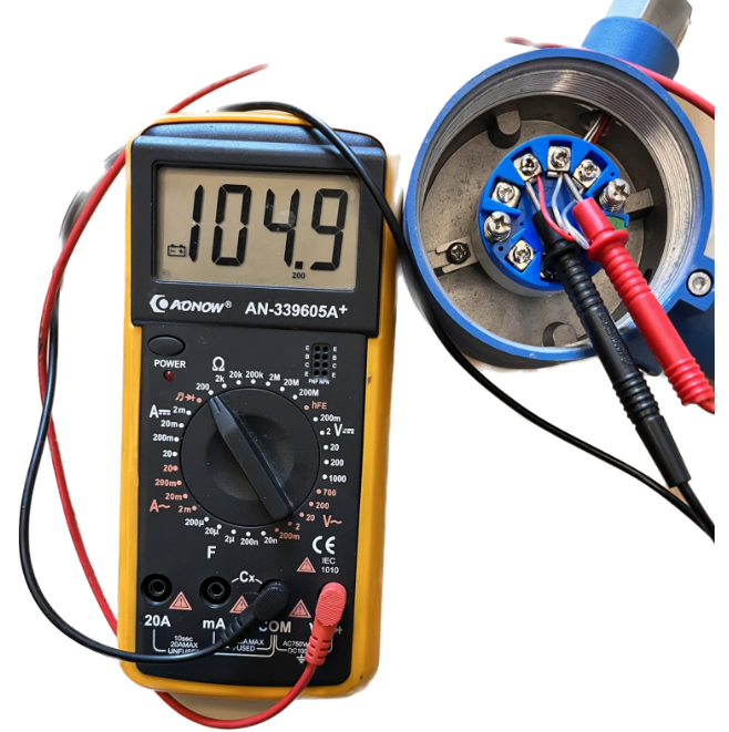
- How to measure DC current with a multimeter
Use a multimeter to measure the current, turn the switch to the milliampere range, determine the positive and negative poles of the circuit, and connect the meters in series circuit. Select a larger range file to reduce the impact on the circuit. - DC method to identify the first and last ends of the stator winding of a three-phase motor
Three-phase motor windings are judged by the head-to-tail DC method. Set the multimeter to the mA range and use a dry battery as a DC power source. One phase winding is connected to the instrument, and the other phase winding is connected to the battery.
The moment the power is turned on, the hands of the watch rotate, and the positive pole is reversed first. If the wiring is not reversed, the remaining phase windings will be treated the same way. - Residual magnetism method to identify the first and last ends of the stator winding of a three-phase motor
The motor that has been running can be judged by the head and tail residual magnetism method. The outlet terminals of the three-phase windings should be marked and connected in parallel. Set the multimeter to the milliampere setting and connect the common point across the parallel connection.
Slowly turn the motor shaft while watching the meter needle. The pointer has no obvious swing, and the three heads and three tails are connected together. The pointer swings to the left and right, with the two heads and one tail joining together.
Replace the ends of one phase winding, and then use the same method to measure and identify. Until the watch hand stops swinging, connect the head and tail together. - Circulating current method to identify the first and last ends of the stator winding of a three-phase motor
The motor that has been running can be judged by the head-to-tail circulation method. The outlet terminals of the three-phase windings are connected in series to form a triangle. Set the multimeter to the mA range and connect it in series to the three-phase winding.
Turn the motor shaft evenly while watching the meter needle. The pointer basically does not swing, and the windings are connected end to end. The pointer swings widely, and one phase winding head is upside down.
The two connection points and the two thread ends are the first and last ends. - Use a multimeter to measure the speed of the three-phase motor
Use a multimeter to measure the speed of the three-phase motor. Open the motor junction box and remove the terminal connecting piece. Connect the multimeter to the milliampere setting and jump across any phase winding.
Rotate the rotor once and watch the pointer swing several times. The two-pole motor swings once and the synchronous speed is three thousand. The four-pole motor swings twice, with a synchronous speed of one thousand and five.
Judging the speed in this way, the speed is slightly lower than the synchronous speed. - Detect the grounding resistance of the grounding protection wire installed in the home
Install a grounding wire at home and test the grounding resistance value. Set the multimeter to the voltage range and connect the kilowatt electric furnace to zero. Measure the terminal voltage of the electric furnace and calculate the operating current value.
Reconnect the electric furnace to the phase-to-ground wire, and then measure the terminal voltage of the electric furnace. The error of the two terminal voltages is divided by the operating current value. Quotient ground resistance value, error of about 5%. - Identify the phase and neutral wires of low-voltage AC power supply
Low-voltage three-phase four-wire system, power supply phase line and neutral line. Set the multimeter to the voltage range, with a measuring range of AC 250. One pen is connected to the ground point, and the other pen touches the power cord. The pointer deflects in a large arc, and the meter pen touches the phase line. The hands of the watch do not move and deflect slightly, and the test lead touches the neutral line.
- Determine the polarity and quality of crystal diodes
To test the polarity of the diode, set the multimeter to the kiloohm range. The measured resistance value is small kilo ohms and the forward resistance of the diode. The black pen touches the positive pole of the tube, and the red pen touches the negative pole of the tube.
The measured resistance value is tens of thousands of ohms and the reverse resistance of the diode. The red stroke takes over the positive pole, and the black stroke takes over the negative pole.
To determine whether the diode is good or bad, set the multimeter to the kiloohm range. The difference between the positive and negative resistance values is large, and the larger the value, the better. The forward and reverse resistance values are close, and the tube under test has failed.
The forward and reverse resistance values are both zero, and the two poles of the tube are short-circuited. The forward and reverse resistance values are infinite, and the tube has an open circuit inside. - Detect the quality of high-voltage silicon stack
Check the quality of the silicon stack and set the multimeter to the voltage level. Silicon stack multimeters are connected in series and connected across to communicate two hundred and two. The measuring range is DC 250, and the silicon stack is connected in the forward direction.
If it is more than 30 volts, it is qualified. If the needle does not move, there is a fault. The measuring range AC is 250 and the reading is 220 short circuit. The needle of the meter does not move and the reading is zero, indicating that there is an open circuit inside the silicon stack. - Determine the quality of capacitors
Microfarad capacity capacitors are easy to judge whether they are good or bad. Set the multimeter to the thousand ohm range and connect the red and black test leads to the two poles. The watch hand moves left and right once, the larger the amplitude, the better.
The needle of the meter does not swing at all, and there is an open circuit in the capacitor under test. The meter needle does not return to zero, and the capacitor under test has broken down. - Use the digital multimeter buzzer to detect the quality of electrolytic capacitors
The quality of electrolytic capacitors is tested with a digital multimeter. Turn the switch to the buzzer, and touch the red and black pens to the positive and negative poles. There is a short buzzing sound, and the overflow symbol is displayed when the sound stops.
The buzzer sounds for a long time and the capacitor has a large capacity. If the buzzer keeps sounding, the capacitor under test is short-circuited. If the buzzer does not sound, the capacitor is internally open. - Safety regulations that should be followed when using clamp ammeters
When using a clamp ammeter, remember the safety regulations. Testing on the high-voltage circuit must be carried out by two people. The potential of the wire being measured does not exceed the voltage level of the clamp meter.
The operation must be done wearing gloves and standing on an insulating pad. There is a charged body on the human head, so keep a sufficient safety distance. Measure the low-voltage bus flow, and add insulation partitions and protection.
It is strictly prohibited to use a clamp meter to measure poor insulation or bare wires. - Use clamp ammeter correctly
Use a clamp ammeter and choose the appropriate model and specifications. For rough measurement on the maximum range, select the range block appropriately. The wire is placed in the center of the jaws, and the dynamic and static cores are well matched.
After the jaws are inserted into the wire, the measuring range cannot be changed while the instrument is powered on. Clamp-type current and voltage meter, measuring current and voltage respectively. The two wires of the lighting circuit should not enter the clamp at the same time.
After each test of the clamp meter, set the measuring range to the maximum range. - Tips for measuring three-phase three-wire current with clamp ammeter
Use a clamp ammeter to measure the three-phase and three-wire current. Kirchhoff gave a certain probability and came up with a technique of measurement. Insert a wire into the jaws and read the phase current value.
The jaws are inserted into two wires and the third phase current is read. The jaws are inserted into three wires and the load balance reads zero. - Tips for measuring AC small current with clamp ammeter
Use a clamp ammeter to measure small AC currents. The insulated wire of the load under test is wound around the jaw core. Divide the reading by the turns plus one to get the true current value. - Detect star-connected three-phase resistance furnace phase failure
If the three-phase resistance furnace has a phase failure, use a clamp ammeter to detect it. The current values of the two phase lines are both less than the rated current. The current in one phase line is zero, and the resistance wire of that phase is blown. - Find short-circuit and ground fault points in low-voltage distribution lines
The low-voltage distribution lines are long and the short-circuit grounding point is difficult to find. Faulty phase line string electric furnace, single control switch to connect the power supply. Use a clamp ammeter to measure the current of the line section by section.
The dividing line between current and non-current is the short-circuit grounding point. - Detection of thyristor rectifier device
Thyristor rectifier device, clamp ammeter detection. Cover the anode connecting wire of the clamp and check the current number on the meter. The meter indicates zero current and the component under test is not working.
The current values of the three-phase components are basically balanced and normal. The current is seriously unbalanced and the phase shift of components is inconsistent. The AC part is faulty and the rectifier transformer is missing a phase. - Detecting cross-phase electricity theft by users
The user’s single-phase electric energy meter measures too little or does not work. Before or after the electric energy meter, the clamp ammeter is used for detection. Clamp the phase line and neutral line, and the meter indication is not zero.
The phase line and neutral line are measured separately, and the current readings vary greatly. Then it is judged as cross-phase electricity theft and one-phase-one-ground electricity theft.
- Safety regulations that should be followed when using an insulation resistance meter to measure insulation.
Use an insulation resistance meter and follow safety regulations. When measuring high-voltage equipment, it must be done by two people. The equipment under test is completely powered off and fully discharged.
When measuring line insulation, permission from the other party should be obtained. Both double-circuit lines are out of power, and measurements during lightning are prohibited. Measure near live equipment and choose an appropriate location for the tester.
Keep a safe distance and pay attention to prevent electric shock. - Use the insulation resistance meter correctly
Use an insulation resistance meter and select the appropriate voltage level. Before the test, all equipment was powered off and fully discharged. The equipment under test should be wiped clean and the surface should be clean and free of dirt.
The location of the anti-meter should be appropriately chosen, away from electric fields and magnetic fields. Place it horizontally without tilting, and test both open and short circuits. Two-color single-core soft leads are not entangled with each other and are well insulated.
The terminal buttons are clearly identified and the test wiring is connected correctly. Shake the handle clockwise, and the speed gradually reaches a constant speed. The shaking measurement time is not fixed, the pointer is stable and the reading is recorded. - Things to note when using an insulation resistance meter for testing
When testing with an insulation resistance meter, there are eight things to keep in mind. During the test, do not touch the wiring buttons with your hands. The glass on the meter head is dusty and should not be wiped during the shake measurement process.
The measuring equipment is insulated from the ground, and the ground terminal is connected to the shell. Shake to measure large capacitive equipment and break away at rated speed. Check the electrolytic capacitor and connect the ground terminal to the positive pole.
For repeated measurements on the same device, it is best to use the same watch. When the shaking measuring equipment is insulated, record the temperature during measurement. It is not suitable for measuring resistance of hundreds of kiloohms, and it is not suitable for use as a general meter. - A diode connected in series prevents the equipment under test from discharging the insulation resistance meter.
Insulation resistance meter terminal button, connected in series with crystal diode. Shake to measure large capacitive equipment to prevent the equipment from discharging current. Eliminate the left and right swing of the watch needle to ensure accurate readings.
After the measurement is completed, the instrument will not be damaged if it stops shaking. - Methods to increase the terminal voltage of the insulation resistance meter
Low voltage insulation resistance meter, connected in series to measure insulation. The series voltage levels are superimposed and the insulation resistance readings are summed. - Insulation absorption ratio of power transformer
The insulation quality of the transformer is judged by the insulation resistance meter. The normal temperature is about 20 degrees, starting from the time of measurement: read the reading in fifteen seconds, and stabilize the value in seconds.
The ratio of the two insulation resistances is called the insulation absorption ratio. If it is greater than 1.3, it is good; if it is less than 1.3, it will be affected by moisture. - Quickly determine the quality of low-voltage motors
If the low-voltage motor is good or bad, open the junction box to check. The insulation resistance meter is shaken to measure the minimum megohm value of the insulation. The reference value is 35 degrees. Divide ten degrees per liter by two.
Multiply it by two for every ten degrees it is lower, and it is better to get a reading that exceeds. Set the multimeter to the mA range and use the star connection method for the motor. The pen of the watch is connected to the two phase heads, and the axis of the hand plate rotates slowly.
The hands of the watch obviously swing left and right, and the results of the three tests are the same. The motor under test is good, otherwise the motor cannot be used. - Use the insulation resistance meter to determine the quality of the high-voltage silicon stack.
The quality of the high-voltage silicon stack can be judged by an insulation resistance meter. The two leads of the circuit are grounded and contact the two ends of the silicon stack. Shake to measure the forward and reverse phase resistors, it is good if the resistance values are very different.
The two readings are very close, indicating that the silicon stack under test has failed. The two readings are infinite, indicating an open circuit inside the silicon stack. The two readings were close to zero, indicating a breakdown and short circuit in the silicon stack. - Insulation resistance meter determines the quality of self-ballasted high-voltage mercury lamps
High voltage mercury lamp is good or bad, kilovolt insulation resistance meter. The two ground leads of the circuit are connected to the two poles of the lamp holder. The mercury lamp is placed in a dark place and the measurement is performed slowly and gradually.
The reading is less than half a megaohm, and the glow inside the bubble is good. The lamp does not emit light and the reading is zero. There is a short circuit inside the mercury lamp. The hands of the meter indicate infinity, and there is an open circuit fault in the lamp. - Insulation resistance meter detects the quality of fluorescent tubes
To measure the quality of fluorescent tubes, use a kilovolt insulation resistance meter. Set the multimeter to the voltage range, with a range of 500 volts DC. The megohmmeter and multimeter are connected in parallel with the same polarity to measure the voltage.
The two leads of the circuit are grounded and connected across the two ends of the lamp. The light is on at rated speed, and it is normal if it is less than 300 volts. The lamp glows a little brightly, but becomes old if it exceeds 300 volts.
If the lamp never shines, it means the lamp is damaged. - Use an insulation resistance meter to determine whether the starter of a fluorescent lamp is good or bad.
Fluorescent lamp starter, insulation resistance meter test. The two leads of the circuit ground are connected to the two poles of the starter. Shake the watch handle slowly and gently, and the neon bulb will discharge and flash red.
The starter under test is in good condition, otherwise the starter is damaged. - Determine whether the line or device is charged or not
A multimeter can be used to determine whether a circuit or device is live. By selecting the appropriate measurement mode and probe contact circuit, the presence and magnitude of voltage can be detected to ensure safe operation.
Usage: Select the voltage measurement mode, touch the probe to the two contacts or conductors to be measured, and read the voltage value on the display. If there is a voltage display, it means the circuit is live.
- Distinguish whether the power supply line is the live wire or the neutral wire
A multimeter can be used to differentiate between live and neutral wires in an AC power supply. This is essential for proper wiring when installing and servicing electrical equipment.
Usage: Select the voltage measurement mode, touch one probe to the wire to be measured, and the other probe to the ground wire or the grounded part of the device, and read the voltage value on the display. If there is a voltage display, it means that the wire under test is a live wire. - Find the breakpoint of the cable
A multimeter can be used to find breaks or faults in cables. This is very useful in electrical wiring troubleshooting and repairs.
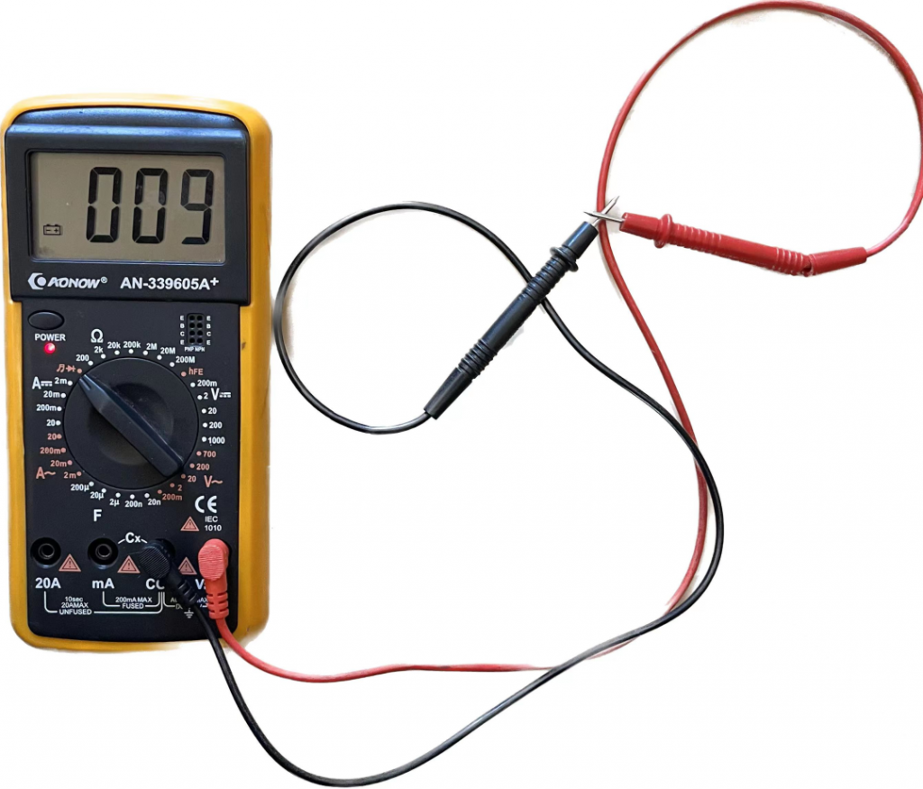
Usage: Select the resistance measurement mode, touch the two probes of the multimeter to the two endpoints of the cable to be measured, and read the resistance value on the display. If the resistance is infinite (open circuit), it means there is a breakpoint.
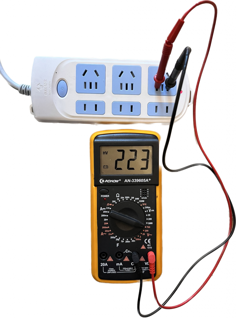
- How to test power quality
A multimeter can be used to test the quality and stability of a power supply to assess its suitability.
Usage: Select the voltage measurement mode, touch one probe to the positive pole of the power supply, and the other probe to the negative pole, and read the voltage value on the display. Observe voltage stability and fluctuations to evaluate the performance of the power supply. - How to detect electromagnetic field radiation
A multimeter can be used to detect the intensity of electromagnetic radiation from surrounding electronic equipment, power lines, or wireless communication equipment.
Usage: Select the appropriate electromagnetic radiation measurement mode and detector, place the multimeter’s detector in the area of interest, and read the electromagnetic radiation intensity value on the display. - How to test battery capacity
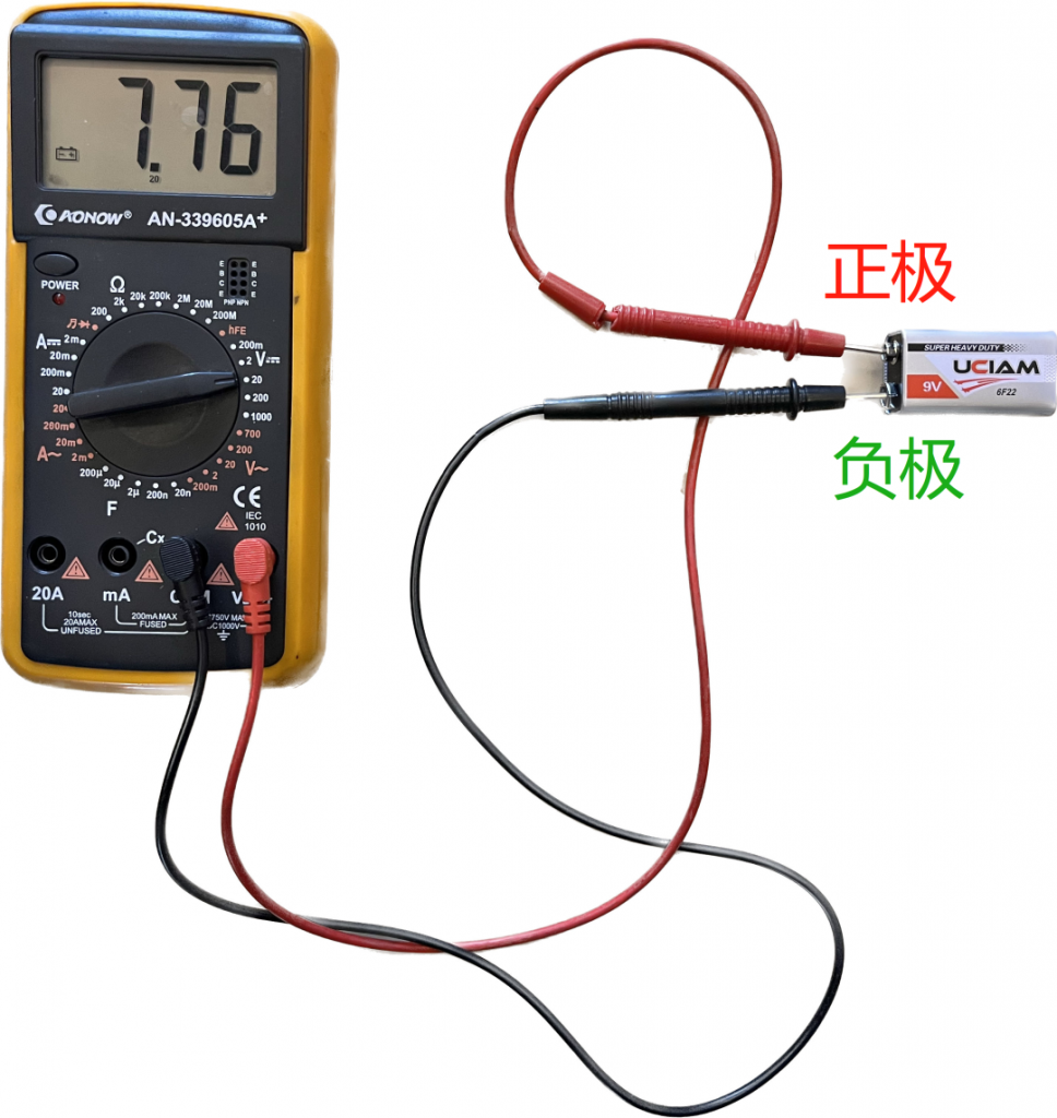
A multimeter can be used to test the capacity of a battery to determine its remaining charge and performance.
Usage: Select the appropriate voltage measurement mode, touch the multimeter probe to the positive and negative terminals of the battery, and read the voltage value on the display. By comparing it to the battery’s nominal voltage, the battery’s capacity condition can be assessed. - Detection of resistance temperature coefficient
A multimeter can be used to measure the temperature coefficient of a resistor, which is how much its resistance changes with temperature.
Usage: Select the resistance measurement mode, touch the probe of the multimeter to the resistive element, and measure its resistance value. The element is then heated or cooled and the resistance is measured again. By comparing the resistance values at two temperatures, the temperature coefficient of the resistor is calculated. - Detect light-emitting diode (LED) polarity
A multimeter can be used to determine the positive and negative polarity of the LED to ensure proper connections.
Usage: Select the diode measurement mode and touch the probes of the multimeter to the two pins of the LED. If a positive voltage value appears on the display, it means the probe is in contact with the positive terminal, otherwise it is the negative terminal. - Test component parameters
A multimeter can be used to test the parameters of the component under test such as the capacitance value of the capacitor and the inductance value of the inductor.
Usage: Select the corresponding measurement mode and range according to the type of component under test. Touch the probe of the multimeter to the pin of the component and read the value on the display to get the parameter value of the component. - Detect fault voltage waveform
A multimeter can be used to detect fault voltage waveforms in a circuit to determine whether there are abnormalities or distortions.
Usage: Select the appropriate voltage measurement mode and range, and touch the multimeter’s probe to the voltage signal in the circuit under test. By observing the waveform graphics on the display screen, problems such as voltage waveform distortion and noise can be detected. - Test logic gate status
A multimeter can be used to test the input and output states of logic gates (such as AND gates, OR gates, NOT gates, etc.) to verify whether the logic operation of the circuit is correct.
Usage: Select the appropriate voltage measurement mode and range, and touch the probes of the multimeter to the input and output terminals of the logic gate respectively. Based on the voltage values on the display, the input and output states of the logic gate can be determined. - Calibrate instruments and equipment
Multimeters can be used to calibrate other instruments and equipment to ensure their accuracy and precision.
Usage: By comparing with a standard source of known accurate values, adjust the measurement range, zero point, gain and other parameters of instruments and equipment so that their output meets the expected accurate values. - Test light intensity
Some multimeters have a light intensity test function that can be used to measure the brightness or illuminance of a light source for lighting design and environmental illumination detection.
Usage: Select the appropriate light intensity test mode and range, and expose the multimeter’s photosensitive element to the light source or lighting environment to be measured. By observing the light intensity value on the display, you can evaluate the brightness level or illuminance value of the light source. - Diagnose sensor failure
Multimeters can be used to diagnose sensor failures, such as temperature sensors, pressure sensors, humidity sensors, etc.
Usage: According to the sensor type and specifications, select the appropriate test mode and range, and connect the multimeter to the sensor. Observing the value or signal changes on the display screen can determine whether the sensor is working properly. - Test pulse width
Some multimeters have the function of testing pulse width, which can be used to measure the high-level or low-level duration of the pulse signal.
Usage: Select the appropriate pulse width test mode and range, and touch the multimeter probe to the positive and negative poles of the pulse signal. By observing the pulse width value on the display, you can evaluate the signal stability and pulse width characteristics. - Test capacitor polarity
In some cases, the polarity of the capacitor may be damaged or unclear.
Usage: You can check the polarity of a capacitor by touching the multimeter’s test pin to both pins of the capacitor. If the voltage displayed is positive, it means the positive terminal is connected to the red test pin and the negative terminal is connected to the black test pin; and vice versa.
- Test the brightness of light-emitting diode (LED)
Usage: The brightness of an LED can be measured by touching the test pin of the multimeter to the two pins of the LED. The brightness of an LED is directly proportional to the current, so the brightness level of an LED can be evaluated by measuring the current. - Detecting faulty capacitors
Usage: Use the capacitance measurement function of your multimeter to detect faulty or damaged capacitors. By measuring the capacitance of a capacitor, you can determine whether it is functioning properly or malfunctioning. - Measuring the phase sequence of three-phase power supply
Phase sequence: Select the voltage test function of the multimeter and connect the test leads to the three phase lines of the three-phase power supply. By reading the voltage values on the display and observing their sequence, you can determine whether the phase sequence of the three-phase power supply is correct. - Detect the pull-in and release voltage of the relay
Usage: Select the voltage test function of the multimeter and connect the test lead to the control terminal of the relay. By changing the control voltage, observe the pull-in and release conditions of the relay to determine its pull-in and release voltage range.