The working principle of high frequency inverter The difference between high frequency inverter and low frequency?
Working principle of high frequency inverter
The high-frequency inverter is a DCtoAC transformer, which is actually a voltage inversion process with the converter. The working principle of the high-frequency inverter is that the converter converts the AC voltage of the grid into a stable 12V DC output, and the inverter converts the 12V DC voltage output by the Adapter into a high-frequency high-voltage AC; both parts are equally The more widely used pulse width modulation (pWM) technique is adopted. Its core part is a PWM integrated controller, the Adapter uses UC3842, and the inverter uses TL5001 chip. The working voltage range of TL5001 is 3.6 ~ 40V. It is equipped with an error amplifier, a regulator, an oscillator, a PWM generator with dead zone control, a low voltage protection circuit and a short circuit protection circuit.
- Input connection [part: the input part has 3 signals, 12V DC input VIN, work enable voltage ENB and panel current control signal DIM. VIN is provided by the Adapter, ENB voltage is provided by the MCU on the motherboard, its value is 0 or 3V, when ENB=0, the inverter does not work, and when ENB=3V, the inverter is in normal working state and DIM voltage is determined by Provided by the main board, its variation range is between 0~5V. Different DIM values are fed back to the feedback terminal of the pWM controller, and the current provided by the inverter to the load will also be different. The smaller the DIM value, the smaller the output current of the inverter. bigger.
- Voltage startup circuit: When ENB is at high level, it outputs high voltage to light up the backlight tube of the panel.
- pWM controller: It consists of the following functions: internal reference voltage, error amplifier, oscillator and pWM, overvoltage protection, undervoltage protection, short circuit protection, and output transistor.
- DC conversion: The voltage conversion circuit is composed of MOS switching tube and energy storage inductor. The input pulse is amplified by the push-pull amplifier and drives the MOS tube to perform switching action, so that the DC voltage charges and discharges the inductor, so that the other end of the inductor can Get the AC voltage.
- LC oscillation and output circuit: ensure the 1600V voltage required for the lamp to start, and reduce the voltage to 800V after the lamp is started.
- Output voltage feedback: When the load is working, the feedback sampling voltage plays a role in stabilizing the voltage output of the inverter.
Classification of high frequency inverters
- Square wave inverter
The AC voltage waveform output by the square wave inverter is a square wave. The inverter circuit used by this type of inverter is not exactly the same, but the common feature is that the circuit is relatively simple and the number of power switch tubes used is very small. The design power is generally between 100 watts and 1000 watts. The advantages of the square wave inverter are: simple circuit, cheap price, and easy maintenance. The disadvantage is that because the square wave voltage contains a large number of high-order harmonics, additional losses will occur in load appliances with iron core inductors or transformers, which will interfere with radios and some communication equipment. In addition, this type of inverter has the disadvantages of not wide enough voltage regulation range, not perfect protection function, and relatively large noise.
- Ladder wave inverter
The AC voltage waveform output by this type of inverter is a step wave, and there are many different lines for the inverter to realize the step wave output, and the number of steps of the output waveform varies greatly. The advantage of the ladder wave inverter is that the output waveform is significantly improved compared with the square wave, and the content of high-order harmonics is reduced. When the ladder reaches more than 17, the output waveform can achieve a quasi-sine wave. When using transformerless output, the efficiency of the whole machine is very high. The disadvantage is that the ladder wave superposition circuit uses more power switch tubes, and some of the circuit forms also require multiple sets of DC power input. This brings troubles to the grouping and wiring of the solar cell phalanx and the balanced charging of the storage battery. In addition, the ladder wave voltage still has some high-frequency interference to radios and some communication equipment.
High Frequency Inverter Features
- Wide input voltage range, high precision voltage regulation, and strong environmental adaptability;
- Adopt special microprocessor control, digital technology, leading in the world;
- Pure sine wave output, excellent electrical performance index;
- LED+LCD liquid crystal display, friendly man-machine interface, intuitive and convenient, can display inverter working status, load status, environmental status and parameters at any time;
- Arbitrarily choose bypass priority or inverter priority;
- The input and output are electrically isolated, which can withstand the surge impact of computer load startup;
- High efficiency inverter, low no-load loss;
- Advanced manufacturing technology, generous and beautiful products;
- With input over, under voltage, reverse connection protection; output overload, short circuit protection; mains bypass high, low voltage and other series of protection;
- In the case of no DC, it can be started by AC;
- Fully automated maintenance, suitable for unattended machine stations.
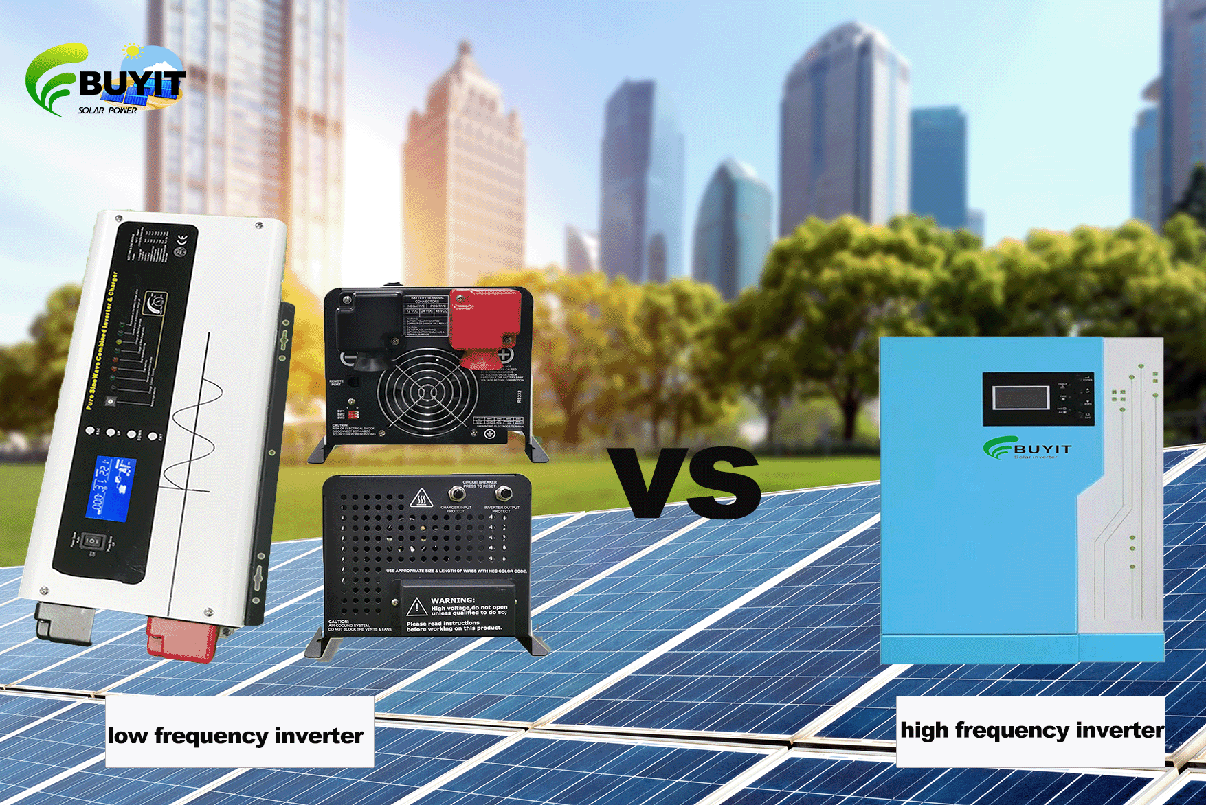
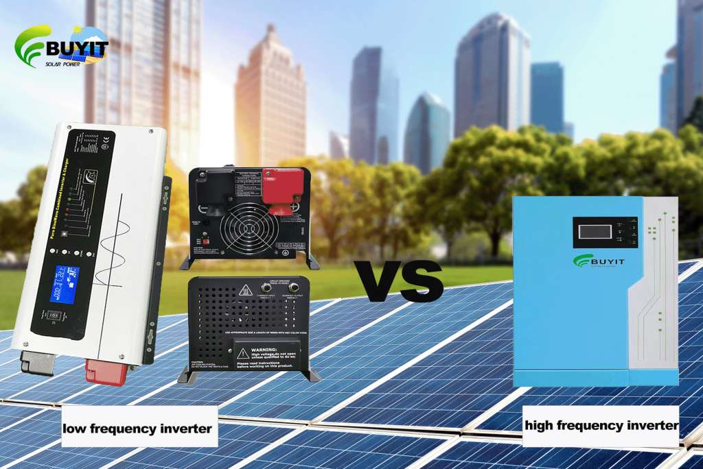
The difference between high frequency inverter and low frequency inverter
- According to the spectrum division table formulated by the Institute of Electrical and Electronics Engineers (IEEE), the low frequency frequency is 30~300kHz, the intermediate frequency frequency is 300~3000kHz, the high frequency frequency is 3~30MHz, and the frequency range is 30~300MHz. , 300~1000MHz is UHF. Compared with low-frequency signals, high-frequency signals change very quickly and have sudden changes; low-frequency signals change slowly and have smooth waveforms.
- The power supply and the signal are different. The voltage provided by the power board generally has a frequency of 0 (DC power supply) or 50Hz (AC power supply). It can be said that the signal is high frequency or low frequency (or other frequencies). It is hard to say on the power board, because it is only used for power supply, and the frequency is very low. If it must be said, it is only low frequency.
- The advantages of high-frequency inverters are mainly light weight, small size, low standby power, and relatively high efficiency (relatively saving electricity). The disadvantage is that the impact resistance is not as good as the power frequency inverter (that is, the low frequency you mentioned), and it may not be able to carry electrical appliances such as food mixers and electric drills. The disadvantage of low frequency is that it is relatively heavy, relatively large, the price may be slightly more expensive, and its own loss will be slightly larger (a little power consumption). The advantage is that it is more solid, and the ability to carry impact electrical appliances will be better.
Both Low and high frequency inverter we have, Pls contact us to get best price!