Analysis of the working principle of the photovoltaic storage and charging MPPT controller
Summary of MPPT working principle
What is an MPPT controller?
MPPT is the abbreviation of “Maximum Power Point Tracking”, which is an upgraded product of the traditional solar charge and discharge controller. Its function is that the controller can detect the power generation voltage of the solar panel in real time and track the highest voltage and current value (maximum power) so that the system can charge the battery with the highest efficiency.
Regarding the maximum power point MPP, the output characteristics of the solar photovoltaic array are nonlinear, and the output is affected by the solar irradiance, ambient temperature and load. Only at a certain output voltage value can the output power of the photovoltaic array reach the maximum value. At this time, the working point of the photovoltaic array reaches the highest point of the output power voltage curve.
Working principle of MPPT controller:
Real-time monitoring: MPPT controller continuously monitors the output voltage and current of solar panels.
Maximum power point tracking: By adjusting the voltage matching between the panel and the battery, the controller finds the maximum power point of the panel (i.e. the operating point with the highest output power).
Voltage adjustment: The controller adjusts the voltage through a DC-DC converter (usually a boost converter) to make the panel work at the maximum power point.
Efficiency optimization: Through this optimization, the MPPT controller can improve the overall efficiency of the solar system, especially when the lighting conditions are poor or the panel temperature is high
Working principle of MPPT-maximum power point tracking: Within a specified period, the microprocessor regularly and actively adjusts the duty cycle D of the PWM to change the output current of the solar cell, thereby causing the output voltage of the solar cell to change, detect the output voltage and output current of the solar cell, calculate the output power of the solar cell array, and then find the position of the maximum power point according to the maximum power point tracking strategy.
The simple model of MPPT is as follows: (Personally, I think its simplest principle is similar to our model for finding the maximum output efficiency of the battery, that is, finding the load point power equal to the internal resistance)
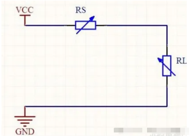
Figure 1 The simplest equivalent model of MPPT principle
RS is the equivalent output resistance of the solar panel, and RL is the equivalent load resistance at the MPPT end. When external conditions change, RS also changes. This is to meet the maximum power output. By adjusting the load resistance at the MPPT end to match it, when RS = RL, the power output is maximum, which is what we call the MPP point. The method of RL following RS changes in real time is called the MPPT algorithm.
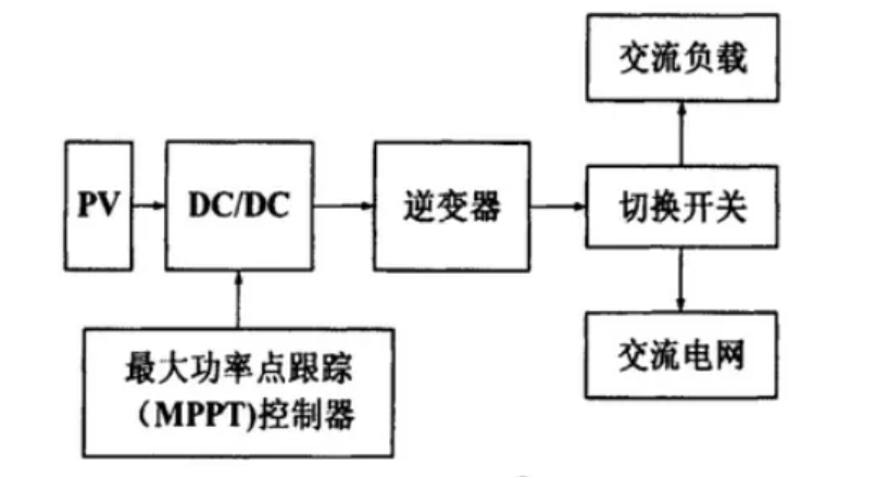
Principle block diagram of inverter with MPPT:
At present, several MPPT methods used in China are: perturbation observation method, conductivity increment method, constant voltage method, short-circuit current method, actual measurement method, linear approximation method, and gap scanning method. The first three are the most commonly used methods. The following is a detailed description of the three methods:
- Perturbation observation method
The principle of the perturbation observation method is: Since the P-V curve of the solar cell can be obtained from the real-time power system, when the solar cell works on the left side of the maximum power point, dP/dV>0 (slope); and on the right side of the maximum power point, dP/dV<0; at the maximum power point, dP/dV=0. Therefore, the control process of the perturbation observation method is: first, let the solar cell work at an initial value Vref, and adjust the DC-DC duty cycle to give the solar cell output voltage a periodic disturbance. For example, the output voltage value (Vref+△V) is disturbed first, and then its power change is measured. Compared with the power value before the disturbance, if the power value increases, that is, dP/dV>0, it means that the photovoltaic works on the left side of the maximum power point. Then the current disturbance direction should be maintained in the next disturbance cycle, and the disturbance should be made in the same +△V direction: On the contrary, if the power value after the disturbance is less than that before the disturbance, that is, dP/dV<0, it means that the photovoltaic works on the right side of the maximum power point. The current disturbance direction will make the working point far away from the maximum power point, so the disturbance direction should be changed and disturbed in the opposite (-△V) direction. After repeated adjustments, the working point of the photovoltaic cell is finally close to the maximum power point.
Advantages: simple control, easy to implement, low requirement for parameter detection accuracy, and the control effect can meet the requirements of the photovoltaic system for maximum power point tracking when the sunshine change is not very drastic.
Disadvantages: Periodic disturbance is required, and once the disturbance direction is determined, the output voltage can only be affected in the next disturbance cycle, which will cause the output of the photovoltaic array to oscillate near the maximum power point, thereby reducing the output efficiency of the system: When the environmental conditions change drastically, misjudgment may occur, resulting in tracking failure. The general control flow chart of the disturbance observation method is shown in the figure below:

Applicable occasions: Environments where the sunshine changes are not very drastic, this is the most commonly used method at present.
Note: The initial value and the given perturbation step have a great influence on the tracking accuracy and speed. When the perturbation step is large, this control method tracks the sunshine changes quickly, but due to the asymmetric characteristics of the photovoltaic device, its output power will produce power oscillation near the maximum power point; when the perturbation step is small, the oscillation of the photovoltaic device output power can be weakened or eliminated, but the tracking speed of sunshine changes will be slowed down. In practical applications, the perturbation step should be selected after experiments.
- Conductance increment method
The conductance increment method is also one of the commonly used algorithms for MPPT control. Its control concept is similar to the perturbation observation method. It also uses the direction of
dP/dV to perform maximum power point tracking control, but the control is different when the solar cell works at the maximum power point.
Principle: From the P-V curve of the solar cell array, it can be seen that the slope at the maximum point Pm is zero, so:
Pm=V*I
The derivative of V on both sides of the equation is:

That is, the condition for reaching the maximum power point, that is, when the change in the system output conductance is equal to the negative value of the output conductance change, the solar cell operates at the maximum power point. The general procedure flow of the conductance increment method is shown in the figure below.
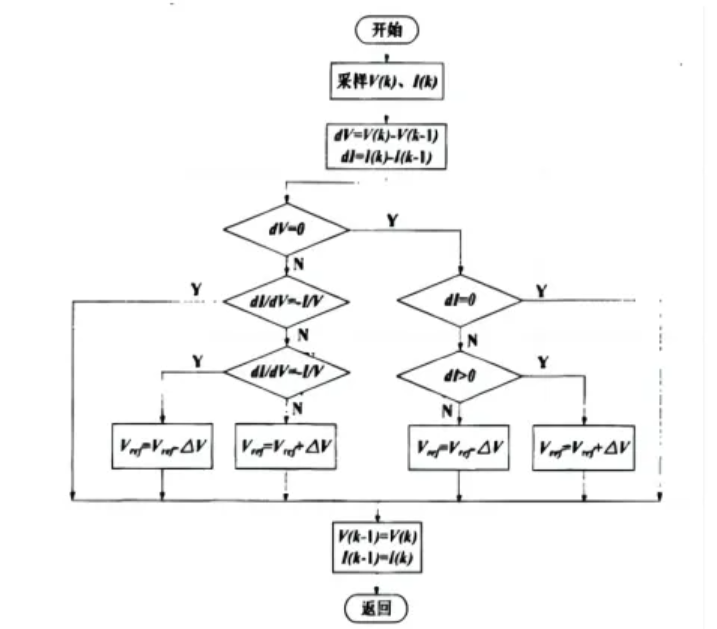
In the figure, V(k) and I(k) are the newly detected voltage and current values, and V(k-1) and Z(k-1) are the voltage and current values detected last time. After the program reads in the new value, it first calculates the error between the new value and the old value, and then determines whether the voltage difference is zero (because the denominator cannot be zero when doing division later). If the voltage difference is zero, then determine whether the current difference is zero. If both are zero, it means that the impedance is consistent and the Vref value remains unchanged. If the voltage difference is zero and the current difference is not zero, it means that the sunshine temperature has changed. If the current difference is greater than zero, the Vref value increases; if the current difference is less than zero, the Vref value decreases. If the voltage difference is not zero, then determine whether the derivative dI/dv=-I/v is valid. If it is valid, it means that the slope of the power curve is zero (maximum power point) and the Vref value remains unchanged; if the conductivity change is greater than the negative conductivity value, it means that the slope of the power curve is positive and the Vref value will increase; otherwise, the Vref value will decrease.
Advantages: precise control and fast tracking speed. When the illumination on the solar cell changes, the output voltage can follow the change in a stable manner, which can basically eliminate the power oscillation phenomenon near the maximum power point caused by the disturbance in the P&O method.
Disadvantages: The algorithm is relatively complex, the hardware requirements are high (especially the measurement accuracy of the sensor is high), and the system response should be fast enough to meet its control requirements, so the corresponding hardware cost will also increase. In theory, the theoretical expression of this method is impeccable. However, when the accuracy of the sensor is limited, the probability of satisfying the derivative is limited, so errors will inevitably occur.
Applicable occasions: In the case of large climate changes.
- Constant voltage method
The constant voltage method (CVT) is a maximum power point tracking control method that uses the characteristic that the working voltage Vm and the open circuit voltage Vo have an approximate proportional relationship when the photovoltaic device outputs the maximum power. Due to its good reliability and stability,
it is still widely used in photovoltaic systems. With the computer and microprocessorization of photovoltaic system control technology, this method is gradually replaced by new methods.
Principle: When the battery junction temperature remains unchanged and the photovoltaic device outputs the maximum power, its working voltage Vm and the open circuit voltage Vo have a fixed proportional relationship Vm=KVo (the ratio K is approximately 0.76~0.8. According to this characteristic of the battery, as long as the open circuit voltage Vo of the battery is known, the working voltage Vm corresponding to the maximum power point can be obtained). The proportional relationship is used to control the MPPT circuit so that the output voltage of the photovoltaic array is equal to Vm. The maximum power output of the photovoltaic device can be achieved. In this way, the MPPT control is actually simplified to voltage stabilization control, which constitutes a constant voltage MPPT control.
Advantages: simple principle, easy to implement, and good stability.
Disadvantages: Ignoring the effect of temperature on the open-circuit voltage of the array, poor control accuracy, especially for the temperature difference between morning and evening and four seasons
Severe regional temperature changes; manual intervention is required for good operation.
Applicable occasions: Usually used in working places with low power and stable sunshine conditions, such as artificial satellites.
For the more information, please contact BUYIT for more details! What’s app:008613808405352