A brief analysis of OBC solutions for new energy vehicles
The major three electric vehicles of new energy electric vehicles refer to the battery, motor and high-voltage “electronic control”, while the minor three electric vehicles refer to the on-board charger (OBC), DC/DC converter (DC/DC converter) and high-voltage DC distribution box ( PDU).
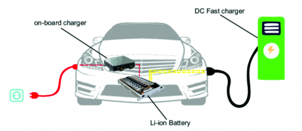
In this article, we analyze the chip solution of the car charger. The on-board charger OBC is one of the core components installed in new energy vehicles. It converts the alternating current output from the AC charging pile into high-voltage direct current to charge the high-voltage power battery of the vehicle. Its power density directly affects the weight of the vehicle. Battery life, charging time, etc., it must also provide necessary protection functions during the charging process, including overvoltage, undervoltage, overcurrent, undercurrent and other protection measures, so that even if an abnormality occurs in the charging system, the power supply can be cut off in time , ensuring the reliability and safety of the charging process, which directly determines the safety and stability of new energy vehicles.
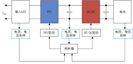
The OBC of new energy vehicles is divided into unidirectional OBC and bidirectional OBC. The circuit includes a power circuit (PFC+ phase-shifted full bridge/LLC) and a control circuit. One-way OBC can only charge the power battery, while two-way OBC can invert the DC power of the power battery into household 220V AC power.
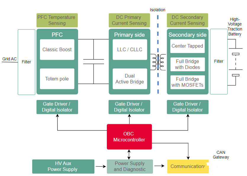
Engineers design an OBC from scratch. The main factors to consider in hardware circuit design include: power factor correction circuit (PFC), primary side DC-DC, secondary side rectification, voltage, current and temperature diagnosis, network (CAN) communication, AC Isolation between power supply, 12V battery and high voltage battery, etc. The key parameters of OBC include: input voltage, power factor, operating efficiency, harmonics, output ripple, output voltage and output current, etc. For specific requirements, please refer to the standard: QC/T 895-2011 Conductive on-board charger for electric vehicles
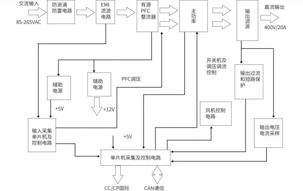
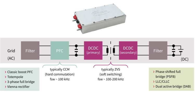
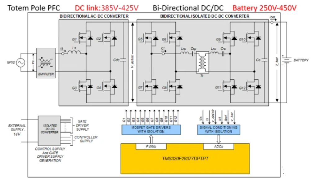
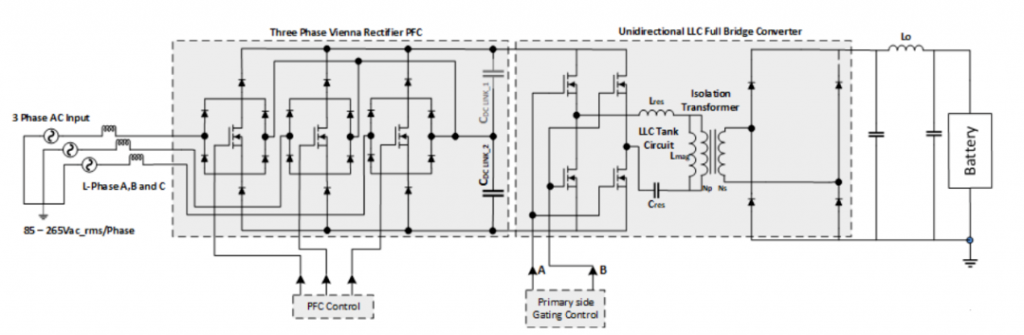
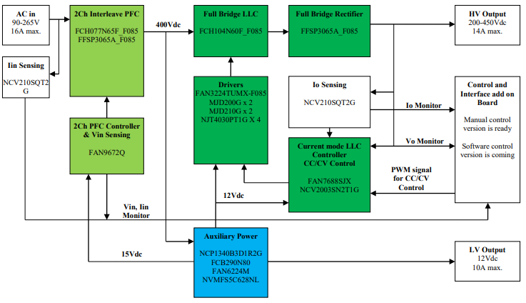
The OBC main loop circuit can usually be divided into two stages. The front stage is a power factor correction PFC module and the rear stage is a DCDC converter. The front stage is a power factor correction PFC module, which performs power factor correction on the input current of the converter to track the input voltage and generate a stable bus voltage, improve the input power factor and suppress high-order harmonics; the rear stage is a DCDC converter. That is, the LLC module provides safe isolation and provides a wide range of voltage or current output to meet the current and voltage requirements for battery charging and achieve electrical isolation.
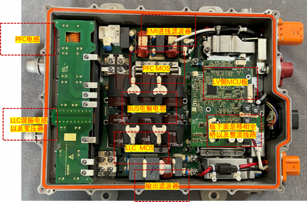
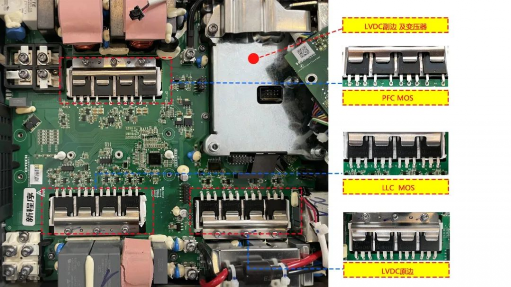
The circuit topology types of OBC post-stage DC/DC converters mainly include Buck, Boost, Buck-Boost, phase-shifted full bridge, resonant converter and other circuit topologies, while the isolated DC/DC converter has poor performance in terms of power level, electrical safety, etc. More suitable for OBC application requirements. Common isolated DC/DC converter topologies mainly include phase-shifted full bridge, dual active bridge circuit, LLC resonant circuit, etc. Electronic components used in OBC include superjunction MOSFET, IGBT, automotive power module (APM), SiC diode, SiC MOSFET, gate driver, regulated power supply, MCU, high-frequency inductor, high-frequency capacitor, high-frequency transformer, isolation devices, various interfaces, vehicle networks, etc. Among them, power semiconductor devices such as diodes, IGBTs, SiC MOSFETs, etc. play a key role in the entire circuit. The power units include: EMI suppression circuit, rectifier circuit, PFC correction circuit, filter circuit, full-bridge conversion circuit, and DC output. circuit etc.
The output power of OBC under the 400V architecture is mostly 3.3kW and 6.6kW; under the trend of 800V fast charging, OBC is developing towards high power (11kW, 22kW, etc.) and bidirectional charging, and DC/DC reliability requirements are upgraded and the usage is increased. Various players in the industry chain have launched two-in-one, three-in-one and even eight-in-one integrated solutions. Currently, the better two-in-one solution is 6.6kW OBC + 1.5kW DC/DC, and the three-in-one solution is 6.6kW OBC + 2kW DC/ DC+PDU. BYD’s eight-in-one high-efficiency electric drive assembly integrates a drive motor, reducer, drive motor controller, DC/DC converter (DC/DC converter), two-way on-board charger (OBC), and high-voltage DC distribution box (PDU), battery management module (BMS), and vehicle controller (VCU).
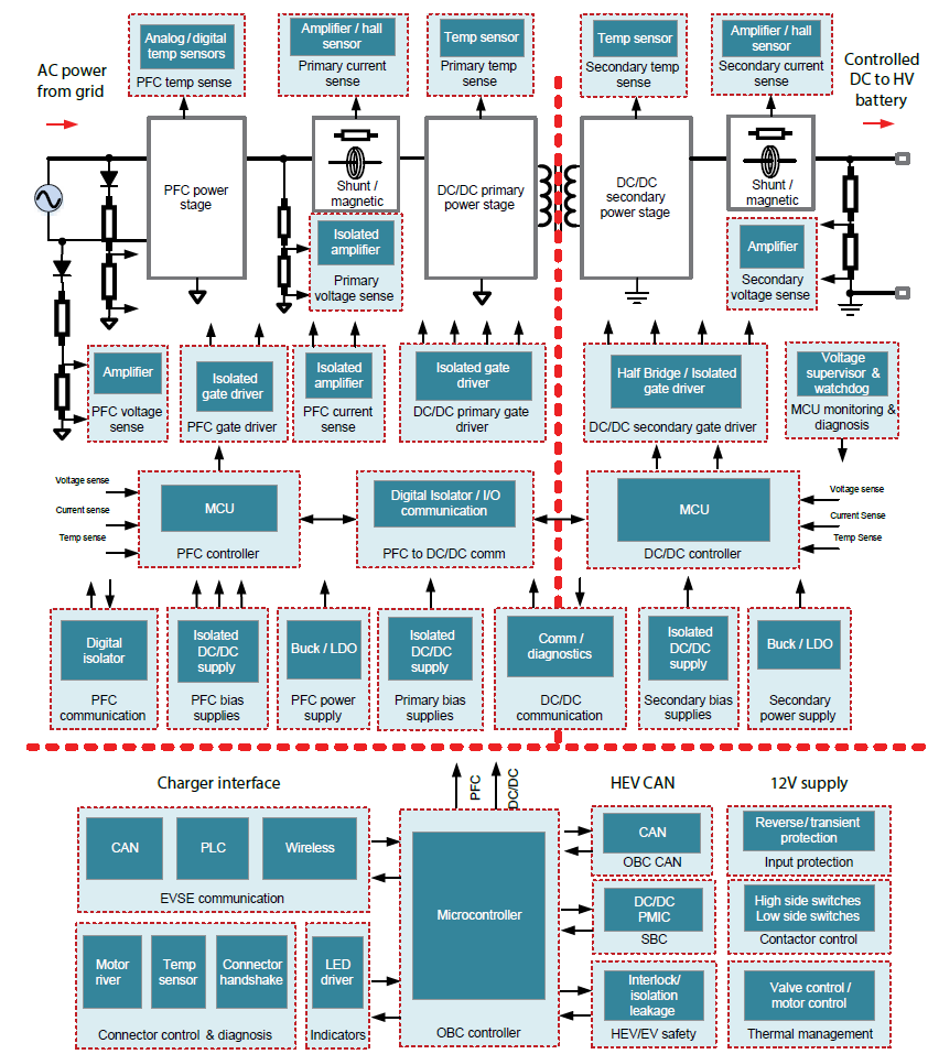
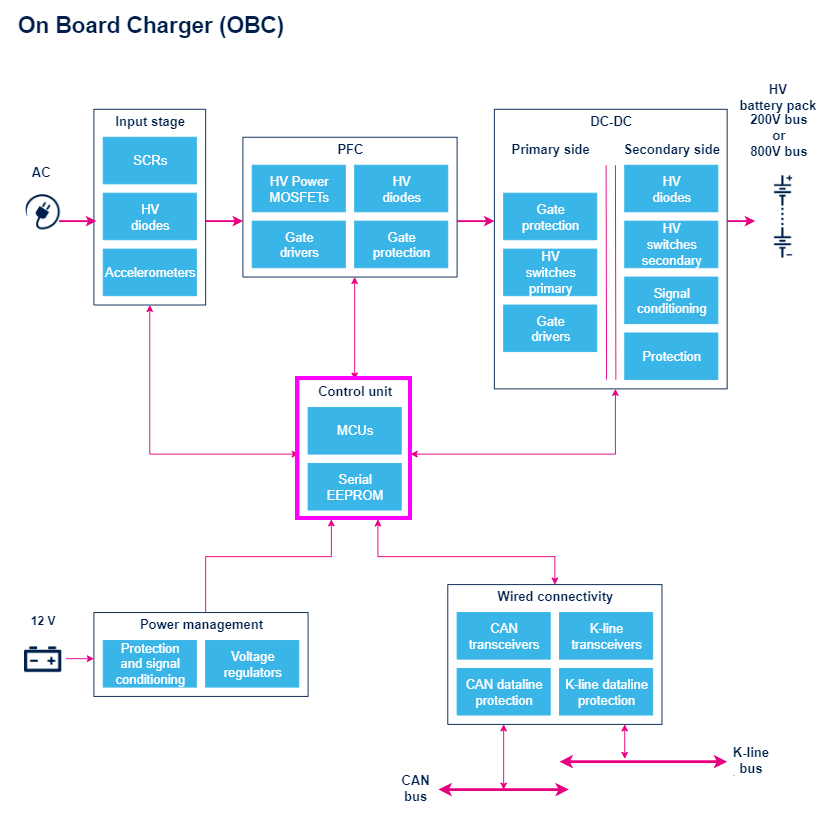
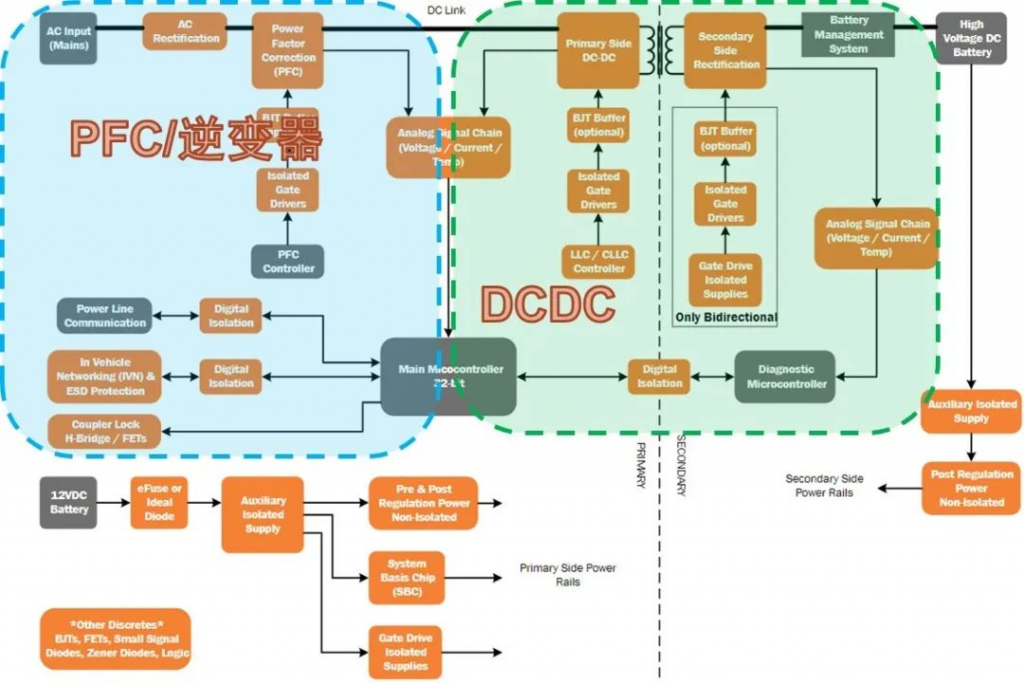
The world’s leading automotive semiconductor manufacturers have launched OBC reference designs. The following are the OBC system block diagrams of each manufacturer: