Shock! The photovoltaic inverter IGBT module suddenly exploded. What is the reason?
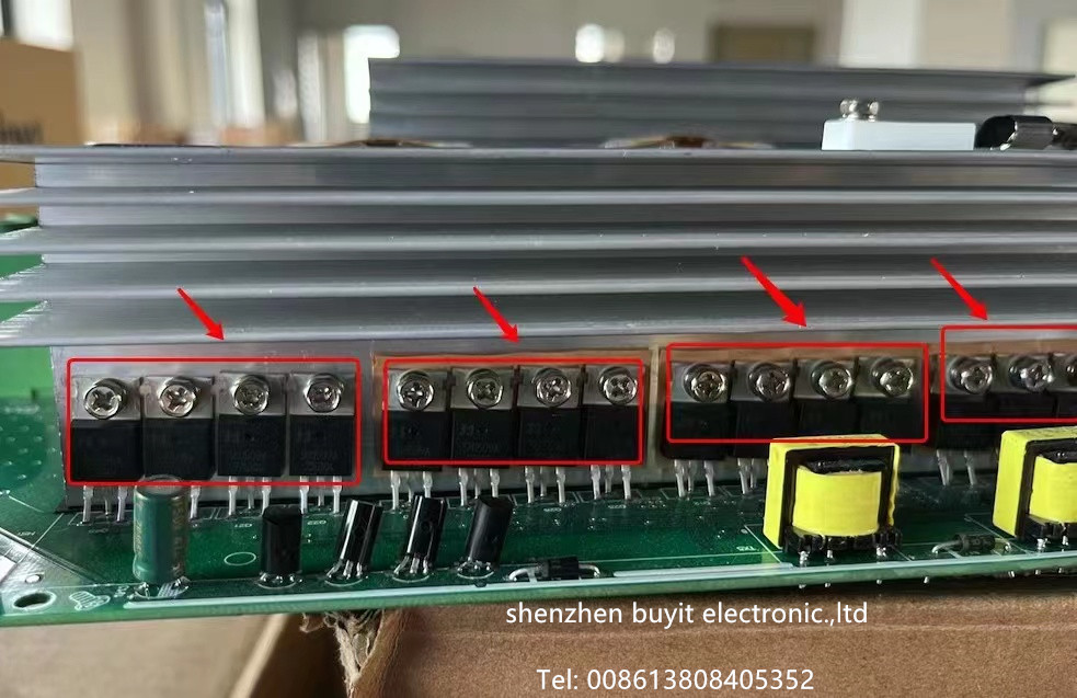
As the core equipment of the solar power generation system, the photovoltaic inverter undertakes the key task of converting direct current into alternating current. The stability of the IGBT (insulated gate bipolar transistor) module, as the core power device of the inverter, directly affects the reliability and life of the entire system. However, the failure of the IGBT module explosion is not uncommon in photovoltaic systems, which can cause equipment shutdown at the least and fire and other safety accidents at the worst.
- Working principle of IGBT module: IGBT module controls on or off by activating or deactivating its gate terminal, thereby changing the outflow direction and frequency of current. IGBT module combines the advantages of MOSFET and BJT, with low on-state voltage drop and fast switching speed, and is an efficient and reliable power conversion device in photovoltaic power generation system.
- Common reasons for IGBT module explosion: The essence of IGBT module explosion is excessive internal loss or external conditions beyond its tolerance limit, resulting in instantaneous overheating, voltage breakdown or current out of control.
The main reasons can be summarized into the following categories: 1. Electrical factors: double impact of overvoltage and overcurrent Overvoltage breakdown: In photovoltaic systems, the peak voltage (such as reverse recovery voltage) generated by grid voltage fluctuations, lightning strikes or line stray inductance at the moment of switching may exceed the withstand voltage limit of the IGBT, causing the insulation layer to break down. For example, at the moment of the inverter being turned off, if the overvoltage formed by the release of the bus inductance energy storage is not effectively suppressed by the absorption circuit, it is very easy to damage the IGBT.
Overcurrent short circuit: When the load changes suddenly, the motor is blocked or the output is short-circuited, the IGBT may withstand a current several times the rated value. If the overcurrent protection circuit does not respond in time (such as the detection delay exceeds 10μs), the module will explode due to instantaneous high temperature.
Abnormal drive circuit: Insufficient drive voltage or signal interference will cause the IGBT to be in an incompletely turned-on state, increase the tube voltage drop and loss, and cause local overheating. For example, when the switch power supply fails and the drive voltage is lower than 10V, the IGBT may burn out quickly due to continuous operation in the amplification state.
- Thermal management failure: insufficient heat dissipation and temperature runaway. IGBTs will continue to generate heat when working. If the heat dissipation design is unreasonable (such as insufficient heat sink area, fan failure or excessively high ambient temperature), the internal temperature of the module may exceed the critical value of 150°C, resulting in a mismatch between the thermal expansion coefficients of the silicon chip and the packaging material, and eventually bursting due to thermal stress. In addition, high temperature will accelerate the aging of the insulation material, further reducing the module’s voltage resistance.
- Design and process defects. Unreasonable circuit design: Failure to configure sufficient buffer circuits (such as RC absorption circuits or TVS diodes), aging of busbar capacitors leading to reduced filtering capacity, will aggravate the impact of voltage spikes on IGBTs.
Process problems: When installing the module, the screws are not tightened, the copper bar stress is uneven, or the welding is poor, which may cause increased contact resistance and local overheating to cause failures.
Improper component selection: The voltage/current margin of the IGBT is insufficient (such as the rated value is only slightly higher than the working conditions), and long-term operation is prone to failure due to small fluctuations. - External environment and operation errors. Grid abnormality: voltage surge, harmonic interference or three-phase imbalance may cause IGBT overload.
Human error: such as wiring error (positive and negative poles are reversed), communication signal error code leading to direct connection of upper and lower bridge arms, or failure to take electrostatic protection measures during maintenance to damage the module.
- Emergency treatment after IGBT explosion: When IGBT explodes, it is necessary to shut down immediately and take the following steps to troubleshoot and repair:
- Safety isolation: Cut off the power supply, check whether there is open fire or smoke, and ensure safety on site.
- Fault location: Check whether the drive circuit voltage is normal (such as drive signal amplitude, dead time);
Measure the bus capacitance and absorption circuit components (such as diodes, resistors) for damage;
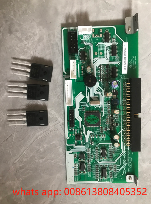
Use a multimeter to detect whether the IGBT module is broken down (CE inter-electrode resistance close to 0Ω indicates a short circuit). - Replace the module: Select an IGBT that matches the original model to avoid uneven current caused by inconsistent batches when used in parallel;
During installation, ensure that the heat dissipation surface is evenly coated with thermal grease, and tighten the screws according to the torque requirements.
4. key measures to prevent IGBT explosion:
1). Optimize circuit design and strengthen protection circuit: connect RC absorption circuit or TVS diode in parallel between CE poles of IGBT to suppress transient overvoltage of switch; configure fast fuse and Hall sensor to achieve fast overcurrent shutdown.
Reasonable selection: The rated voltage of IGBT should be more than twice the operating voltage, and the current margin should consider the load peak (such as the instantaneous output fluctuation of photovoltaic array).
- )Improve heat dissipation efficiency Use forced air cooling or liquid cooling system to ensure that the module operating temperature is lower than 125℃;
Clean the dust of radiator regularly and check the running status of fan. - )Standardize operation and maintenance management Regular inspection: Use infrared thermal imager to monitor IGBT temperature distribution, use oscilloscope to observe the driving signal waveform, and find abnormalities in advance.
Anti-interference design: Optimize PCB layout to avoid crossing of power line and signal line; use shielded cable and magnetic ring to suppress electromagnetic interference. - )Strengthen personnel training and system monitoring. Provide IGBT working principle and fault diagnosis training to operation and maintenance personnel to improve emergency response capabilities;
Deploy a real-time monitoring system to collect bus voltage, current and IGBT temperature data and set threshold alarms.
5: The explosion of IGBT modules in photovoltaic inverters is indeed a thorny problem, and there are many reasons. In order to ensure the stable operation of photovoltaic power generation systems and the use of equipment for a longer time, we must study why IGBT modules explode, and then prescribe the right medicine to prevent and deal with them. In this way, we can reduce the risk of problems with IGBT modules and make photovoltaic power generation systems more reliable and safer.
If you have any questions about the reasons for the explosion of IGBT modules in photovoltaic inverters, or have other experience in dealing with faults, please leave a message in the comment area. Let’s learn and improve together with BUYIT!


